What is the difference between an overload and a short circuit?
What is the difference between an overload and a short circuit?
An overload is too much current flowing through the normal circuit path over time. A short circuit is current taking an abnormal low-resistance path, often producing a sudden spike many times higher than the overload case. Both are overcurrent events, but they stress the system in very different ways and require different protective responses.
Why confusing these two failure modes leads to the wrong protective device in the panel
The reason this distinction matters is that the protective response has to match the fault. An overload is a moderate excess - maybe 120% or 150% of the circuit's rated current - sustained over seconds or minutes. It generates heat that accumulates in conductors, insulation, and contact surfaces. Left unchecked, it shortens the life of the cable and the connector, softens insulation, and eventually creates conditions for a more serious failure down the line. But the current itself is not dramatically higher than normal, so the system can look and feel fine for a long time before anything visibly fails.
A short circuit is a different animal. It happens when current bypasses the intended load entirely - a damaged conductor touches a grounded enclosure, two phases bridge inside a junction box, or insulation breaks down inside a connector. The resistance drops close to zero, and the current spikes to whatever the supply can deliver. In an industrial system fed by a large transformer or generator, that can mean thousands of amps in the first few milliseconds. The protective device has to respond fast enough to interrupt that current before it destroys the conductor, the connector, or the device itself.
What actually happens inside the cable and the connector during each type of fault
During an overload, the primary mechanism is thermal. The conductor heats up gradually, and the heat migrates outward through the insulation. If the overload is modest and short, the insulation absorbs it and recovers. If the overload is sustained, the insulation softens, ages, and eventually fails at its weakest point. Connectors experience the same progression - the contact surfaces heat, the housing expands, and the contact pressure changes subtly with each thermal cycle. Over many overload events, a connector that was once tight becomes loose, which raises its resistance, which generates more heat, which accelerates the problem. This is the slow degradation cycle that makes overloads harder to catch than short circuits.
During a short circuit, the forces involved are electromagnetic as well as thermal. The sudden current spike produces magnetic forces between conductors that can physically move wires inside an enclosure, crack connection points, and weld contacts together inside a connector or a breaker. The thermal energy delivered in the first fraction of a second can be enough to vaporize small conductors or melt contact surfaces. There is no gradual buildup - the damage is immediate. This is why short circuit protection has to act in milliseconds, not seconds.
In practice, many field failures start as one and become the other. A connector that has been slowly degraded by repeated overload cycles develops a high-resistance spot. That spot heats aggressively, breaks down the surrounding insulation, and eventually creates a short circuit path. The overload was the slow cause; the short circuit is the fast consequence.
How to tell which failure mode you are looking at on a real job site
The signs of an overload history are gradual and cumulative: discolored insulation, a faint burnt smell on a cable or connector body, contacts that feel loose when mated, or a breaker that trips after running for a while and resets fine. These are the markers of sustained thermal stress, and they often show up in connectors and cables that have been in rental service for a long time. The temptation is to reset the breaker and move on, but the underlying overload condition is still there.
The signs of a short circuit are more dramatic: a breaker that trips instantly on the first attempt to energize, visible arc marks or melted material inside a connector or junction, a fuse that has blown with visible discoloration, or a cable with a hard lump at a specific point where the conductors bridged internally. Short circuit evidence is usually obvious and localized, and the circuit should not be re-energized until the fault path is found and repaired.
Where KUPO Power's connectors sit in the overload and short circuit protection chain
Every connector in a circuit is part of the rated chain that overcurrent devices are sized to protect - and that connector layer is what KUPO Power builds. K-LOK 400A and K-LOK 150A single-pole cam-type connectors are KUPO's equivalents to the Camlok ecosystem standard in North American touring and film. PowerFit 400A is the Powersafe-pattern keyed single-pole connector (KSPC) used in European stage and event power. CEE Form connectors cover the IEC 60309 international pin-and-sleeve standard. Choosing a connector rated to match the cable and the upstream protective device keeps both the overload and the short circuit protection chain intact. The KUPO Power 101 FAQ Hub covers the full coordination picture.
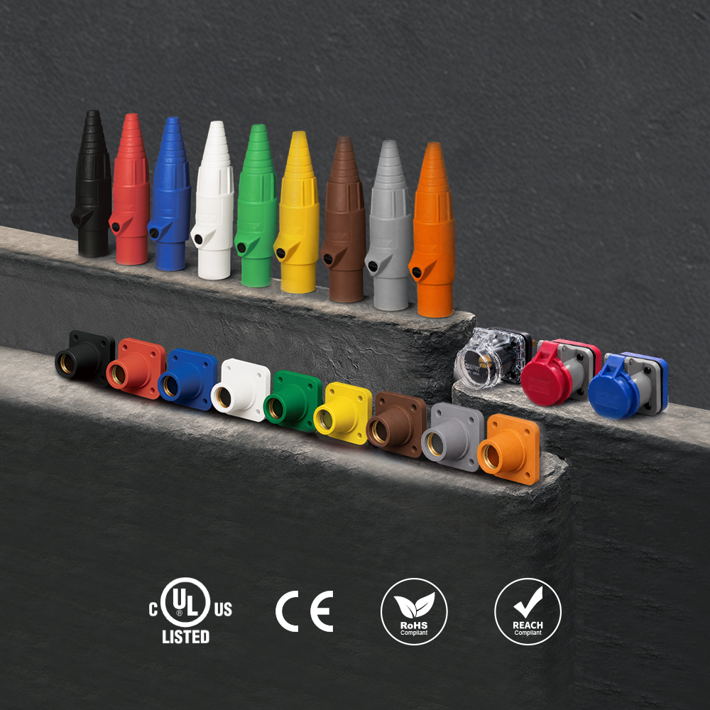 K-LOK 400A Single-Pole Cam-Type Connectors
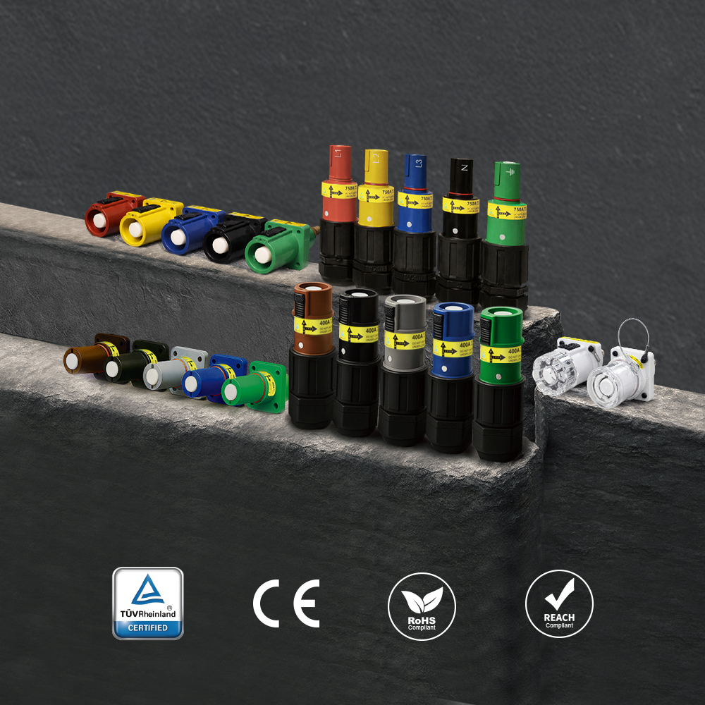 PowerFit 400A Keyed Single-Pole Connectors
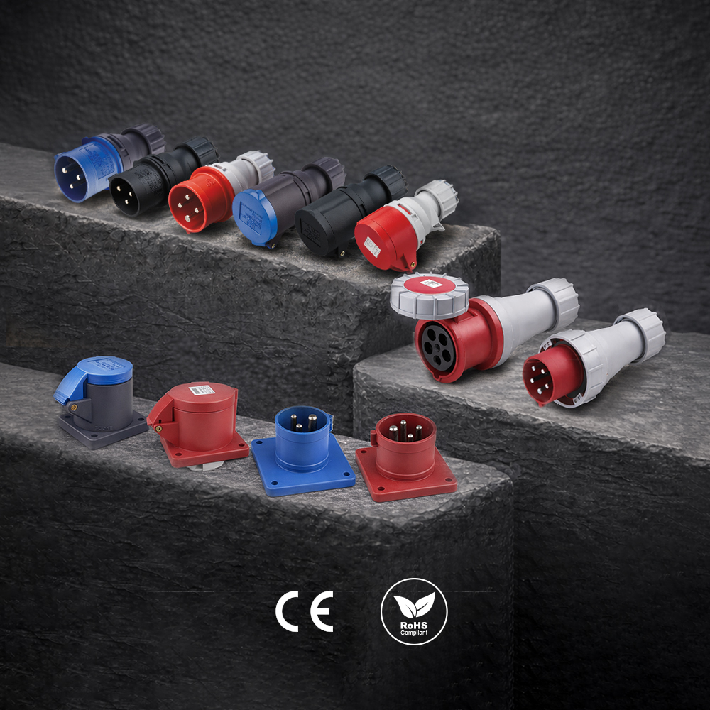 CEE Form Connectors
Have a Question?
Explore the full KUPO Power 101 FAQ Hub for answers to 30 more common questions about industrial power, or ask our team directly about your application.
