What is ampacity, and why does it matter?
What is ampacity, and why does it matter?
Ampacity is the maximum current a conductor can carry continuously under defined conditions without exceeding its safe temperature limit. It matters because the number printed on a cable label is a starting point, not a guarantee - the actual safe current depends on installation conditions that the label cannot predict.
Why a cable's current rating is really a temperature rating in disguise
Every conductor generates heat when it carries current. The heat comes from resistive losses in the metal itself - current flowing through a conductor with finite resistance produces power loss proportional to the square of the current. That heat has to go somewhere. It migrates outward through the insulation, through any surrounding conduit or bundling, and eventually dissipates into the surrounding air or surface. The cable's insulation has a maximum temperature it can withstand before it starts to degrade - typically 60, 75, or 90 degrees Celsius depending on the insulation type.
Ampacity is the current at which this thermal equilibrium lands exactly at the insulation's rated temperature under a set of assumed conditions: a specific ambient temperature, a specific installation method, and no other heat sources nearby. Change any of those assumptions and the equilibrium shifts. A cable rated for 100 amps at 30 degrees Celsius ambient may only be safe for 80 amps at 40 degrees ambient, because the higher starting temperature leaves less thermal headroom before the insulation limit is reached. The physics are simple. The consequences of ignoring them are not.
How ampacity tables are built - and what they assume about your installation
The ampacity tables published in electrical codes like the NEC (National Electrical Code, used in North America) or the IEC 60364 series (used internationally) are the result of thermal modeling and testing under standardized reference conditions. For the NEC, the baseline assumptions typically include an ambient temperature of 30 degrees Celsius, a single cable or a defined number of conductors in a raceway, and adequate ventilation. The IEC tables use similar but not identical reference conditions.
These assumptions are reasonable for a large number of installations, but they are assumptions nonetheless. A cable run across a sun-baked rooftop in the middle of summer is not operating at 30 degrees ambient. A bundle of six feeder cables lashed together on a cable bridge at a live event is not a single conductor in free air. A cable coiled on a reel and never fully unwound is trapping its own heat. In every one of these cases, the table value overestimates the safe current because the real conditions are thermally worse than the reference conditions the table was built on.
This is not a flaw in the tables. They are designed to be adjusted. The codes provide correction factors for higher ambient temperatures, adjustment factors for bundled conductors, and engineering guidance for unusual installation methods. The table gives you the starting number. The correction factors give you the real number. Using the table value without the corrections is the most common way ampacity gets misapplied in the field.
The practical signs that a cable is running too close to its ampacity limit
A cable operating near its thermal limit does not trip a breaker or flash a warning light. The signs are physical and often subtle. The first sign is warmth. A cable that is noticeably warm to the touch in the middle of a run - not just at the connector terminations where some warmth is normal - is dissipating more heat than it should. If it is too hot to hold comfortably, the insulation is already being stressed.
The second sign is at the terminations. Connectors and lugs at the ends of overloaded cables tend to run hotter than the cable itself because the contact resistance at the termination adds heat on top of the cable's own losses. Discolored insulation near a connector, a connector body that smells faintly of heated plastic, or a lug that shows oxidation are all signs that the thermal budget is being exceeded at that point.
The third sign is long-term: insulation that has become stiff, brittle, or cracked on cables that are only a few seasons old. This is the hallmark of chronic thermal aging - the cable has been running above its safe temperature often enough that the insulation has lost its flexibility. In rental and touring equipment, this kind of degradation is a signal that the cable has been asked to do more than its ampacity allows, repeatedly, without anyone catching it in time.
Where KUPO Power's connectors fit into the ampacity conversation
The connector at each end of a cable run is part of the thermal chain - its contact resistance adds heat, and its current rating has to be coordinated with the cable's ampacity and the upstream protective device. That connector layer is what KUPO Power builds. K-LOK 400A and K-LOK 150A single-pole cam-type connectors are KUPO's equivalents to the Camlok ecosystem used in North American touring, film, and live event work, where high-current feeder runs make ampacity coordination critical. PowerFit 400A is the Powersafe-pattern keyed single-pole connector (KSPC) standard in European stage and event power. CEE Form connectors cover the IEC 60309 international pin-and-sleeve standard. Matching connector rating to cable ampacity is what keeps the weakest link in the thermal chain from becoming a failure point. For the full picture of how cable, connector, and protection ratings work together, the KUPO Power 101 FAQ Hub covers the complete system.
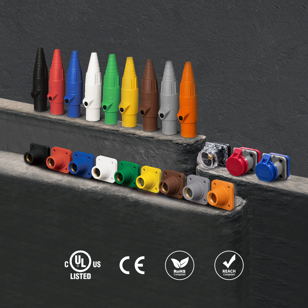 K-LOK 400A Single-Pole Cam-Type Connectors
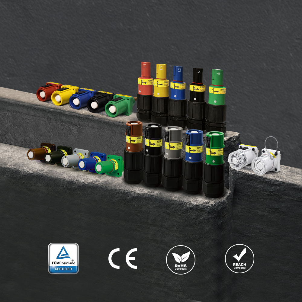 PowerFit 400A Keyed Single-Pole Connectors
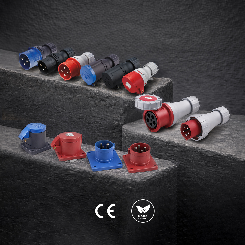 CEE Form Connectors
Have a Question?
Explore the full KUPO Power 101 FAQ Hub for answers to 30 more common questions about industrial power, or ask our team directly about your application.
