Why is load-breaking capability an important connector selection issue?
Why is load-breaking capability an important connector selection issue?
Not every connector is designed to be connected or disconnected while carrying current. If a connector without load-breaking capability is opened under load, the resulting arc can pit and erode the contact surfaces, damage the housing, and create a safety hazard for the person handling it. Connector selection has to reflect how the connector will actually be used in the field, not just its nominal current rating on a datasheet.
What happens inside a connector when it is opened under load - and why the damage is cumulative
When two contacts separate while current is flowing between them, the current does not stop the instant the metal surfaces part. Instead, it arcs across the widening air gap for a brief period before the gap becomes large enough to extinguish the arc. That arc is a small, intensely hot plasma channel - temperatures at the arc point can reach several thousand degrees for the fraction of a second the arc persists. Each time this happens, the arc melts and vaporizes a tiny amount of material from the contact surface. Over many cycles, the contacts develop pitting, craters, and a layer of oxidized debris that raises the resistance of the connection even when the connector is fully mated.
The cumulative effect is what makes this dangerous. A connector that has been opened under load a few dozen times may still mate and appear functional, but its contact resistance has crept upward. Higher contact resistance means more heat during normal operation, which accelerates further degradation. Eventually the connector reaches a point where it overheats even at currents well below its original rating. The arc damage from disconnecting under load is the initial cause; the thermal runaway during normal use is the downstream consequence.
The difference between connectors designed for load-breaking and those that are not
Connectors designed for load-breaking include mechanical or material features that manage the arc during disconnection. Some use silver-plated or specially alloyed contacts that resist arc erosion. Others use a mechanical sequence that breaks the circuit at a specific point in the disconnection travel, sometimes through a pilot contact that opens last and absorbs the arc energy. Still others rely on the speed and geometry of the disconnection to stretch and extinguish the arc quickly.
Connectors that are not designed for load-breaking are optimized for a different set of priorities: low contact resistance, high current capacity, mechanical durability, and ease of mating. Their contacts may be copper or copper alloy without the arc-resistant plating or geometry that load-breaking designs require. These connectors are perfectly safe and effective when connected and disconnected in a de-energized state. The problem only arises when they are used in a workflow that involves hot connections or disconnections.
The distinction is not about quality. A well-made connector with no load-breaking rating is not inferior to one that has it. It is designed for a different use case. The issue is when the field use case does not match the design intent - when a connector rated for dead-front mating is routinely opened and closed under load because the workflow demands it or the crew does not have time to kill power before reconfiguring.
How to decide whether a load-breaking rating matters for a given application
The question to ask is simple: will this connector ever be connected or disconnected while the circuit is energized? In permanent installations where power is always switched off before maintenance, load-breaking capability may not be a selection driver. In temporary installations - touring rigs, film sets, live events - the answer is often yes. Circuits are reconfigured during the show, loads are moved between outputs, and the pressure to keep things running means connectors get pulled while they are still carrying current.
In those environments, selecting connectors with an appropriate load-breaking rating is not optional. It is part of matching the connector to the real operating conditions, the same way you match the current rating to the actual load and the cable size. A connector that can carry 400 amps but cannot be safely disconnected at 400 amps is not a 400-amp connector for that application - it is a connector that requires a specific operating procedure every time it is handled. If the procedure is not followed consistently, the result is cumulative arc damage, degraded contacts, and eventually a connection that fails during normal use.
Where KUPO Power's connectors address the load-breaking question
The load-breaking behavior of a connector depends on its design, its contact metallurgy, and how it is specified for the application - and the connector layer is what KUPO Power builds. K-LOK 400A and K-LOK 150A single-pole cam-type connectors are KUPO's equivalents to the Camlok ecosystem used across North American touring, film, and live event work, where hot-swap workflows are common and contact durability under repeated mating cycles matters. PowerFit 400A keyed single-pole connectors (KSPC) serve the Powersafe ecosystem in European stage and event power, where the keyed mechanical design adds a layer of mating sequence control. CEE Form connectors follow the IEC 60309 standard, which includes pin-and-sleeve geometry designed to manage the disconnection sequence. Choosing the right connector family for the way it will actually be used in the field - not just its nominal rating - is what keeps the connection safe over its full service life. For the broader picture of how connector selection, protection, and cable sizing all fit together, the KUPO Power 101 FAQ Hub covers the full system.
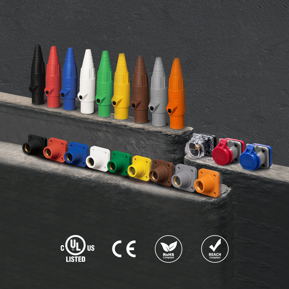 K-LOK 400A Single-Pole Cam-Type Connectors
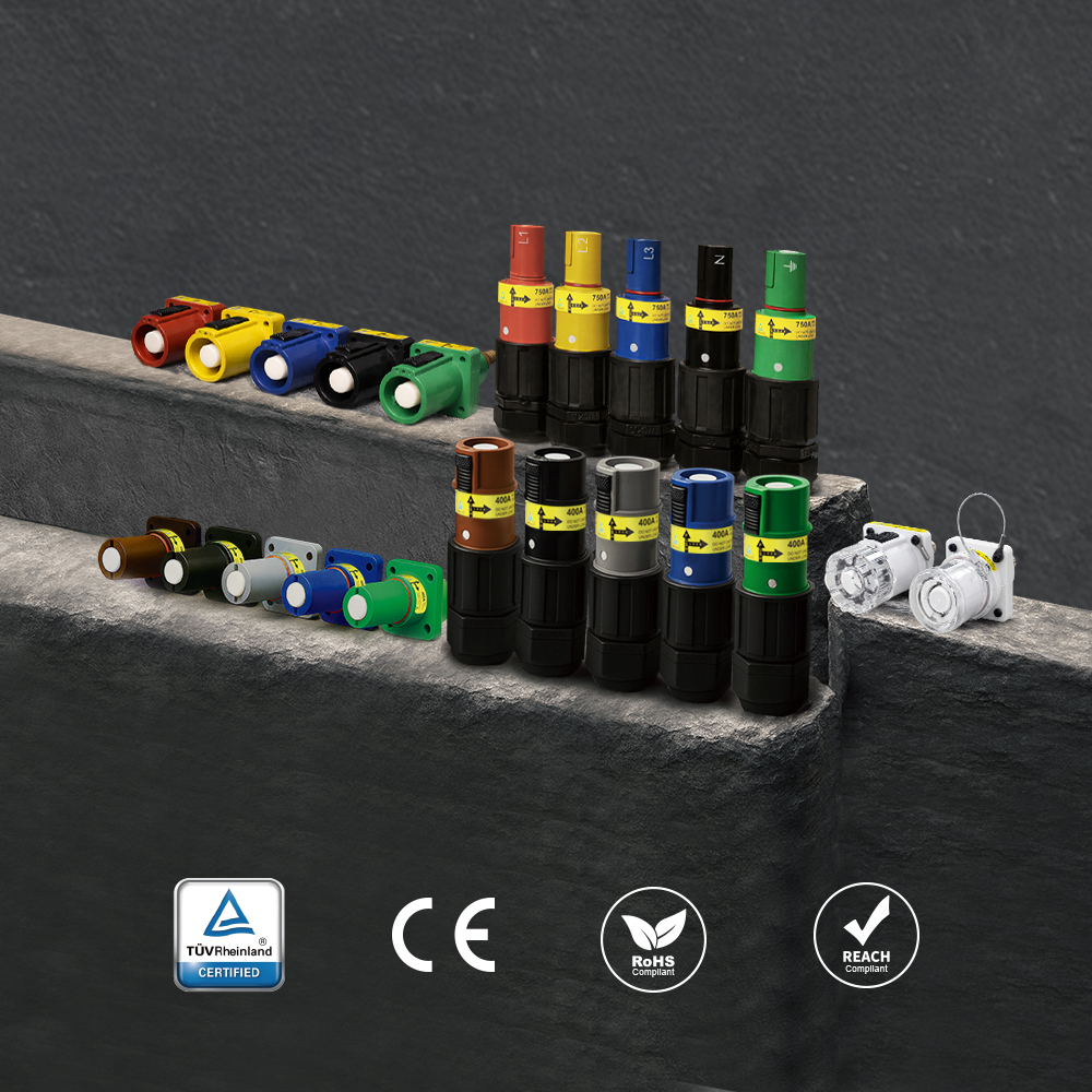 PowerFit 400A Keyed Single-Pole Connectors
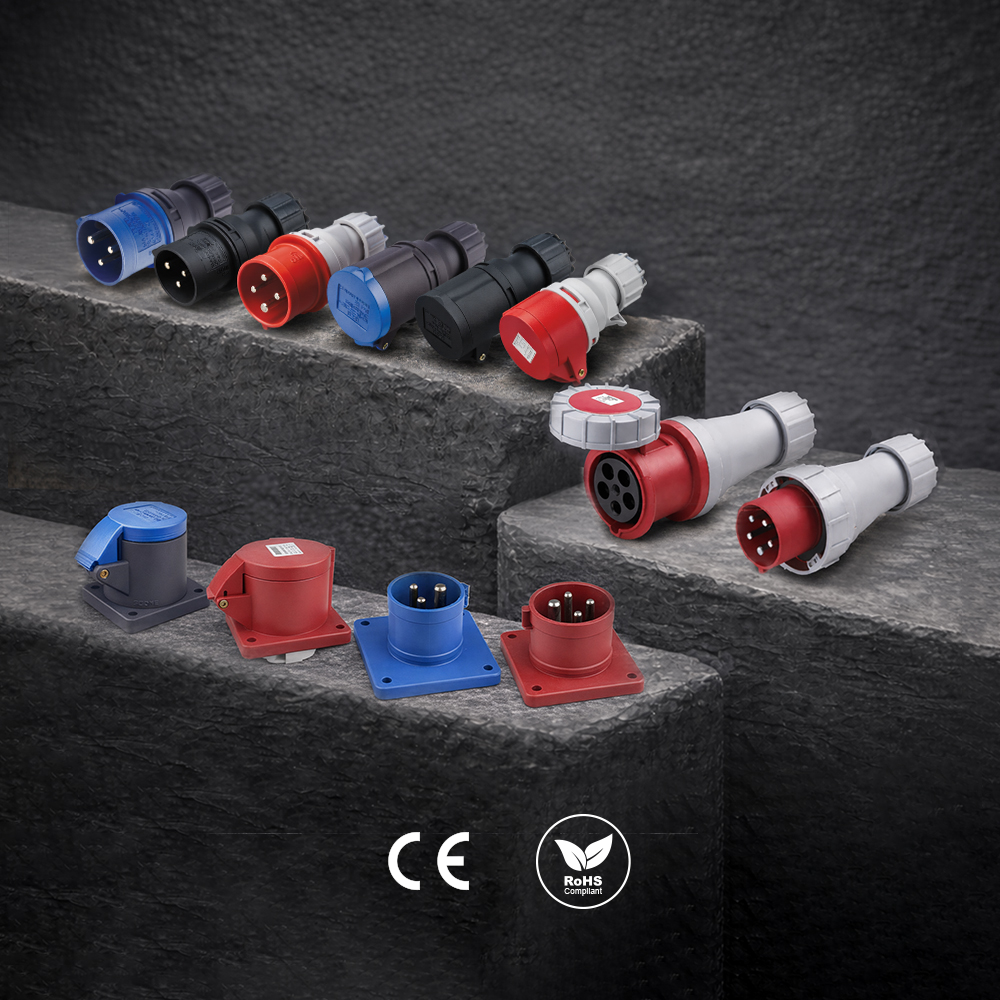 CEE Form Connectors
Have a Question?
Explore the full KUPO Power 101 FAQ Hub for answers to 30 more common questions about industrial power, or ask our team directly about your application.
