What is a continuous load, and how does it affect system design?
What is a continuous load, and how does it affect system design?
A continuous load is any load expected to draw its maximum current for three hours or more without interruption. The distinction matters because heat accumulates over time - a conductor, connector, or protective device that handles a short-duration load comfortably may overheat under the same current held for hours. Most electrical codes require that continuous loads be served by conductors and protective devices rated for at least 125% of the continuous current.
Why the same current that is safe for an hour can become unsafe for a full day
When a cable or connector first starts carrying current, the heat generated by resistive losses begins to raise the temperature of the conductor, the insulation, and the contact surfaces. For the first several minutes, the temperature climbs steeply. Then it begins to level off as the heat dissipating into the surroundings approaches equilibrium with the heat being generated. In many installations, that equilibrium temperature is close to but safely below the insulation's rated limit.
The problem with continuous loads is that the thermal equilibrium under sustained current is higher than the equilibrium under intermittent current. A load that cycles on and off gives the conductor and the connector brief recovery periods where the temperature drops back toward ambient. A load that runs continuously holds the temperature at its peak without interruption. The insulation, the connector housing, and the contact surfaces see their highest sustained temperature, and every component ages fastest at its highest temperature. This is not a dramatic failure mode - it is a slow one. The cable that runs warm all day, every day, ages faster than one that runs warm for two hours and then rests.
Where the 125% rule comes from and what it actually requires
The NEC and most other major electrical codes address continuous loads with a sizing rule: the conductor and the overcurrent protective device serving a continuous load must be rated for at least 125% of the continuous load current. If a load draws 80 amps continuously, the conductor and the breaker must be rated for at least 100 amps. The extra 25% provides the thermal margin that sustained operation consumes.
The rule applies to both the conductor and the protective device because both are affected by the sustained heat. A breaker operating at 100% of its rating under a continuous load will run hotter than the same breaker carrying the same current in short bursts. Most standard breakers are tested and listed for use at up to 80% of their nameplate rating under continuous conditions - which is the same as saying the load should be no more than 80% of the breaker, or equivalently, the breaker should be at least 125% of the load. Some breakers are specifically listed for 100% continuous duty, meaning they can operate at their full nameplate rating without the 125% upsizing. These are less common and typically more expensive, but they exist for applications where the 125% rule would force an impractical jump in conductor and panel size.
The connector at the end of the circuit is part of the same thermal chain. A connector operating at 100% of its rating under a continuous load will reach a higher steady-state temperature than one that sees the same current intermittently. The contact resistance at the mating surfaces generates heat that adds to the conductor's heat, and over hours that cumulative temperature determines whether the connection stays healthy or begins to degrade.
How to identify continuous loads in real installations and size accordingly
In many industrial and entertainment power applications, the continuous load threshold is easy to hit. Lighting rigs that run for an entire show, LED walls that stay on for a full broadcast day, HVAC equipment that runs around the clock, base-load processing equipment in a factory - all of these qualify as continuous loads. Even loads that seem intermittent can qualify if their duty cycle is high enough that the thermal effect is equivalent to continuous operation.
The sizing exercise starts with the actual measured or calculated load current, not the nameplate of the equipment. A dimmer rack with a nameplate rating of 100 amps but an actual average draw of 60 amps is a 60-amp continuous load for sizing purposes (assuming it runs continuously). The conductor and protection are sized to 125% of 60 amps, which is 75 amps - not 125% of the nameplate. Oversizing to the nameplate is safe but wasteful. Undersizing to the actual draw without the continuous load margin is the mistake that causes slow thermal degradation over months or years of service.
Where KUPO Power's connectors fit into the continuous load design
In every circuit carrying a continuous load, the connectors at each connection point are part of the thermal chain that the 125% rule is designed to protect - and that connector layer is what KUPO Power builds. K-LOK 400A and K-LOK 150A single-pole cam-type connectors are KUPO's equivalents to the Camlok ecosystem used in North American touring, film, and live event work, where all-day lighting and LED loads are the norm. PowerFit 400A is the Powersafe-pattern keyed single-pole connector (KSPC) standard in European stage and event power. CEE Form connectors cover the IEC 60309 international pin-and-sleeve standard. Choosing a connector rated with adequate margin above the continuous load current keeps the contact temperature safely below the threshold where thermal aging accelerates. For the full picture of how cable, connector, and protection sizing work together, the KUPO Power 101 FAQ Hub walks through the complete system.
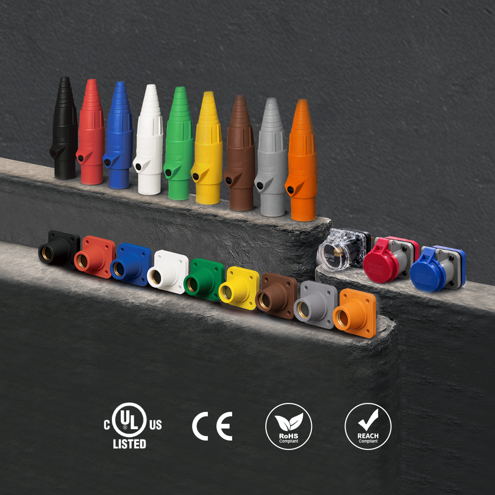 K-LOK 400A Single-Pole Cam-Type Connectors
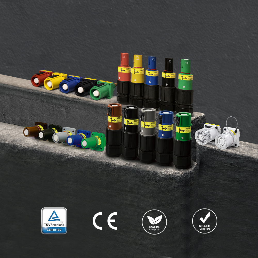 PowerFit 400A Keyed Single-Pole Connectors
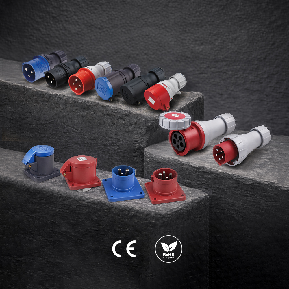 CEE Form Connectors
Have a Question?
Explore the full KUPO Power 101 FAQ Hub for answers to 30 more common questions about industrial power, or ask our team directly about your application.
