What signs suggest a connector or termination may be overheating?
What signs suggest a connector or termination may be overheating?
Common warning signs include discoloration, melting, cracking, burnt odor, loose parts, or visible deformation. Unexpected voltage drop or localized heating during inspection can also indicate a problem. Overheating should be treated as a warning of improper loading, poor termination, degraded contact condition, or component mismatch. Catching these signs early prevents equipment damage and fire risk.
Visual and physical warning signs of connector overheating
Discoloration is usually the earliest warning sign. When current flows through a connection with high resistance, heat is generated at the pin-socket interface. A blue or red connector body may develop a light brown or tan stain around the contact area. Brass contacts may develop a black or purple oxide film. This discoloration signals that interface temperature has climbed into the range where material degradation begins. Melting is a more severe sign that overheating is well underway. Thermoplastic connector bodies will soften and deform if local temperature exceeds the material's softening point, typically around 80 to 100 degrees Celsius. The body may look swollen or warped, or socket contacts may be visibly pushed out of alignment. Cracking is another critical sign. When a connector body gets hot and then cools rapidly, the plastic shrinks at a different rate than the metal parts inside, creating stress and cracks. A cracked connector body has compromised insulation and is a shock hazard. A burnt odor near a connector is a definitive sign of thermal damage. The plastic and contact materials produce distinctive smells when burned. If you smell this near a connector, it means the connection has reached high enough temperature to break down the material and the circuit should be shut down immediately.
Electrical signs and system-level causes of overheating
Unexpected voltage drop across a connector is an electrical indicator of high contact resistance. In normal operation, a K-LOK 400A connector operating at rated current should have a voltage drop of only a few millivolts. If you measure the voltage at plug and socket using a multimeter and the difference is larger than expected, the contact resistance is higher than it should be. This high resistance generates heat. By monitoring voltage drop across connectors - called preventive electrical inspection - technicians can identify problem connections before overheating becomes visually obvious. Infrared inspection reveals overheating that may not yet be visible to the naked eye. An infrared camera shows temperature variations across the connector surface. If the area around the contact zone is noticeably warmer than the rest of the body, heat is being generated at the interface. Spot-checking connectors with an infrared gun during setup in touring or film operations can catch overheating problems early.
Intermittent power loss or flickering loads can signal connector overheating. When connection resistance is borderline high, voltage may be adequate when current is steady, but as the connection warms and resistance increases, voltage sags and loads begin to flicker or dim. The crew temporarily solves the problem by loosening and retightening the connector, which momentarily restores contact, only to have the problem recur minutes or hours later. This pattern - intermittent faults that improve briefly when the connector is disturbed - is a classic sign of high-resistance connection that is overheating.
Overheating at a connector is never caused by the connector alone. A properly designed and installed connector operates at ambient temperature plus a small rise due to resistive heating. If a connector is overheating, something is wrong with the circuit or termination. Improper loading (drawing more current than the connector is rated for) is one possibility. A K-LOK 150A connector carrying 200 amps is overloaded and will overheat. Poor termination (weak or incorrect solder joints, incorrect crimp pressure) increases contact resistance at the conductor-to-contact interface. Degraded contact condition (oxide buildup, corrosion, mechanical wear) increases pin-to-socket interface resistance. Component mismatch (low-quality connector paired with higher-quality, or mixing manufacturers with different geometries) can create loose fit and high contact resistance. In touring and film operations, overheating often surfaces because feeder cables from different sources are connected together or a connector has been in service for years with relaxed contacts. In broadcast facilities, overheating can appear suddenly if a load previously within system rating is switched on or a connector was not mated all the way. In rental power systems, overheating warnings are common if inventory has been used hard and not maintained well.
KUPO Power connectors and system reliability
KUPO Power K-LOK 400A and K-LOK 150A connectors are designed with precise contact geometry and material properties that minimize contact resistance and keep interface temperature low under rated current. Socket contacts are made from material with high spring force and stable properties so contact pressure remains consistent across years of use. Pin geometry is engineered to compress socket contacts reliably with each mating cycle. PowerFit 400A connectors follow the same design principles for Powersafe-pattern applications, and CEE Form connectors maintain precision across the IEC 60309 specification. Because KUPO Power connectors are engineered to keep contact resistance low, they generate less heat during normal operation. However, even high-quality connectors can overheat if termination is poor, the connector is mismatched with its mate, or the circuit is overloaded. This is why overheating is always a system warning. If you observe discoloration, melting, cracking, burnt odor, loose parts, unexpected voltage drop, or localized heating, the circuit should be disconnected and the underlying cause addressed. Include regular infrared inspection as part of setup and maintenance for high-current feeder systems. For guidance on troubleshooting overheating and building reliable power systems, visit the KUPO Power 101 FAQ Hub.
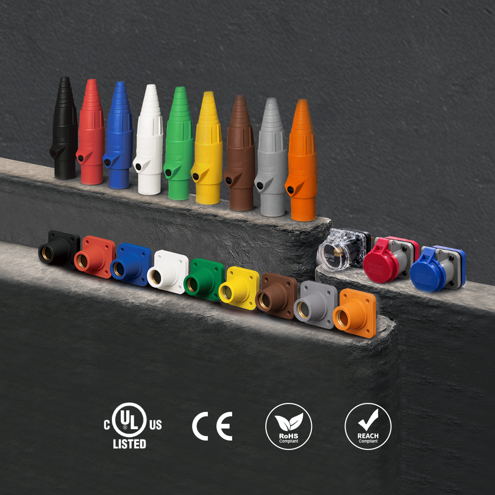 K-LOK 400A Single-Pole Cam-Type Connectors
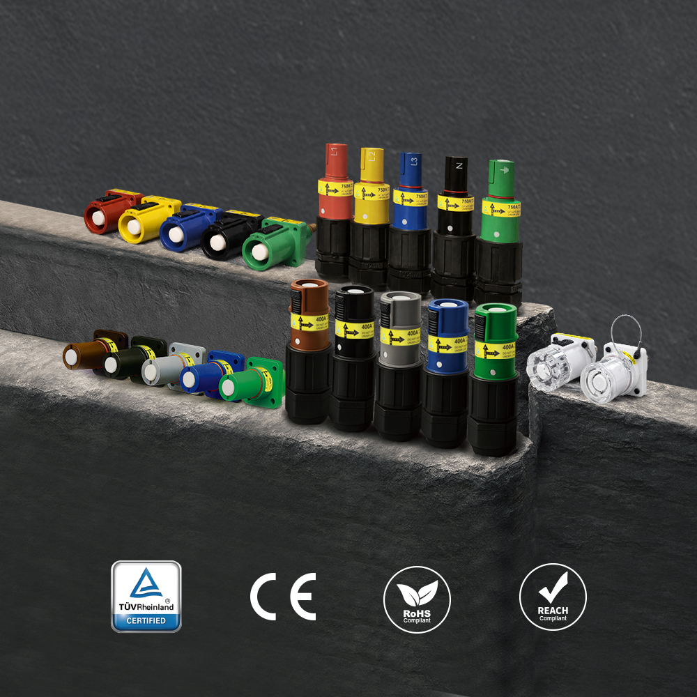 PowerFit 400A Keyed Single-Pole Connectors
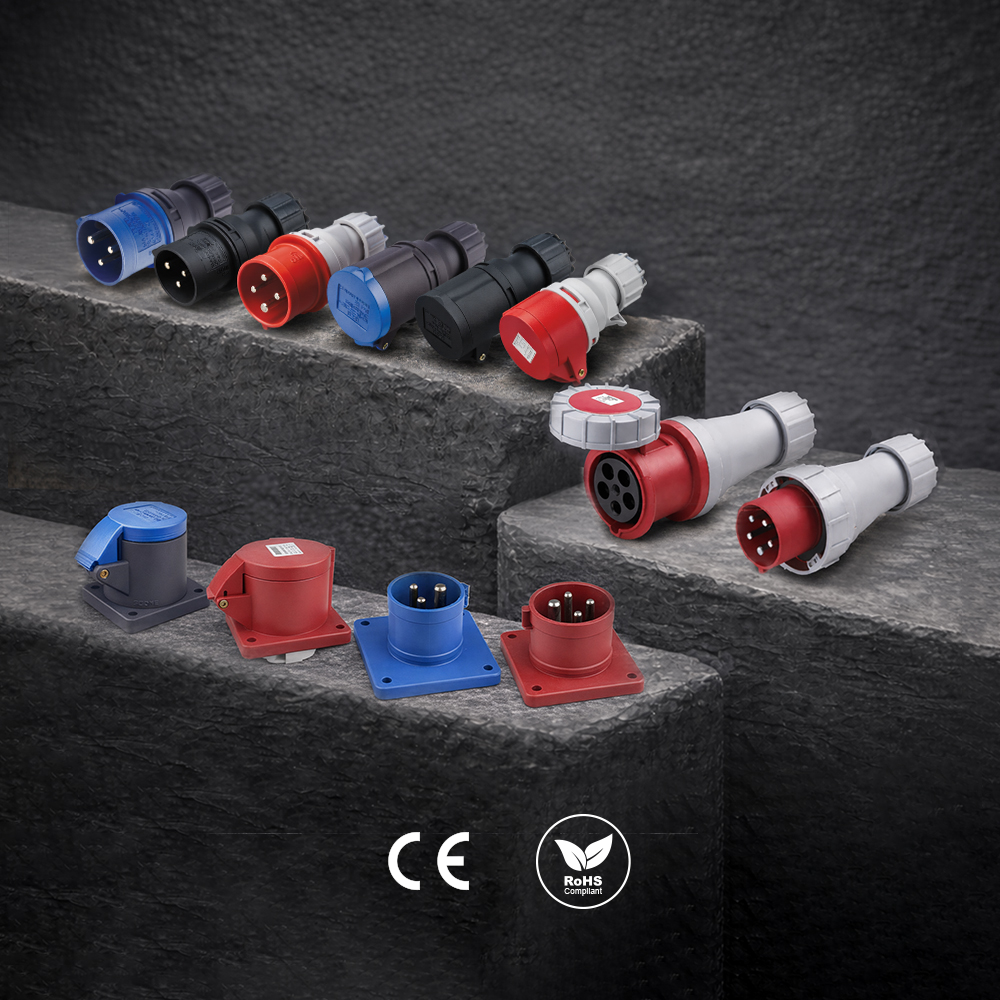 CEE Form Connectors
Have a Question?
Explore the full KUPO Power 101 FAQ Hub for answers to 30 more common questions about industrial power, or ask our team directly about your application.
